| Home > Recording Systems Central > SystemFlow Software for Talon Recording Systems |
|
|
Software for Talon Recording Systems
|
|
SystemFlow® is the software interface that is integrated into every Talon® recorder. SystemFlow software provides three ways to allow the user to configure and control a Talon recorder:
SystemFlow software allows the recorder to be set up to run autonomously by implementing scripts using the API or telnet interface. All three interfaces can be run from a remote connection over Gigabit Ethernet and all allow for easy access to recorded files. | |||||||||||||||||||||||||||||||||||||||||||
|
| The ArchiTek™ FPGA Development Suite allows FPGA design engineers to add custom IP to a number of Pentek's Talon recording systems. FPGA IP can be added to the recorder to provide real-time, on-the-fly digital signal processing during the data acquisition process, greatly reducing the time associated with post-processing recorded data. ArchiTek provides a simple development environment that allows engineers to add FPGA IP such as threshold detection, spectral filtering, digital downconversion, demodulation or any other digital signal processing technique required. |
The software includes the graphical user interface (GUI) that is used to control the recorder with point-and-click configuration management, a client/server communication interface, NTFS file system support and an application programming interface (API) for custom user applications and control. Signal analysis tools include a virtual oscilloscope, spectrum analyzer, and spectrogram to monitor signals before, during, and after data collection.
The SystemFlow GUI provides intuitive configuration screens for simple setup of the system hardware and allows users to store their settings as profiles. An integrated signal viewer provides a virtual oscilloscope, spectrum analyzer and waterfall display to allow for analysis of signals prior to, during and after recording.
SystemFlow is only available as an integrated component of Pentek's Talon Recording Systems. It is not available as a standalone product.
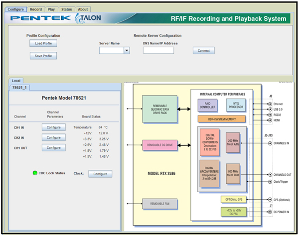
The SystemFlow GUI provides the user with a control interface for the recording system.
The user can easily move between screens to set configuration parameters, control and monitor a recording, play back a recorded signal and monitor board temperature and voltage levels.
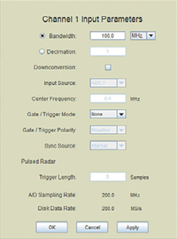
SystemFlow Hardware Configuration InterfaceThe SystemFlow Configure screen provides a simple and intuitive means for setting up the system parameters. The configuration screen shown here, allows user entries for bandwidth, digital downconversion, center frequency, decimation, as well as gate and trigger information. All parameters contain limit checking and integrated help to provide an easy-to-use, out-of-the-box experience. |
|
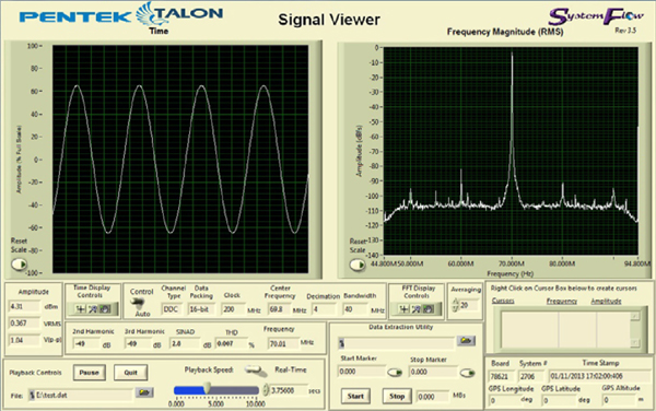
The SystemFlow Signal Viewer includes a spectrogram display, a virtual oscilloscope and spectrum analyzer for signal monitoring in both the time and frequency domains. It is extremely useful for previewing live inputs prior to recording, and for monitoring signals as they are being recorded to help ensure successful recording sessions. The viewer can also be used to inspect and analyze the recorded files after the recording is complete.
Advanced signal analysis capabilities include automatic calculators for signal amplitude and frequency, second and third harmonic components, THD (total harmonic distortion) and SINAD (signal to noise and distortion). With time and frequency zoom, panning modes and dual, annotated cursors to mark and measure points of interest, the SystemFlow Signal Viewer can often eliminate the need for a separate oscilloscope or spectrum analyzer in the field.
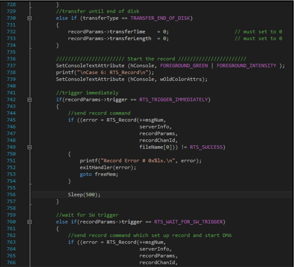
Pentek's SystemFlow API (Application Programming Interface) allows you to develop your own User Interface (UI) for controlling your Talon recording system. The API is a C-callable library that allows you to control the recorder from an application interface that you develop. If you want to develop your own UI, the SystemFlow Simulator provides a means of testing your UI before you receive your Talon Recorder. This is very helpful for development programs that are on a tight schedule.
Below is an example of controlling recording via the SystemFlow API.
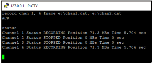
The Talon telnet facility is an optional feature that can be requested when ordering one of Pentek's Talon recording systems. The Talon telnet facility allows you to control a Talon recorder from a remote computer. You also can use the Talon recorder's SystemFlow Signal Viewer to remotely monitor real-time data.
Pentek's Telnet Facility for Talon Recording Systems User's Guide provides instructions for setting up telnet access and describes all the supported commands.
Below is an example of use of the "record" command:
|
|
Simulator for Talon Recording Systems |
|
Pentek's SystemFlow Simulator software package simulates the SystemFlow® recording software, which is installed on all Talon® recording systems. You can download and install the free SystemFlow® Simulator to your desktop or laptop PC. The SystemFlow Simulator allows you to learn how to use the Talon recording system's SystemFlow software interface before you acquire a recorder or while you are waiting for delivery of a Talon recording system. The Simulator can simulate the operating environment of all the different Talon recorder models. |
 Login or register to download the free SystemFlow Simulator |
The Simulator uses the same client-server architecture as every Talon recording system, thereby allowing you to use either the SystemFlow GUI (Graphical User Interface) or SystemFlow API (Application Programming Interface) to control the system. In this way, the Simulator allows you to experience how the system operates exactly as you would experience using an actual system in the field.
The Server is responsible for the real-time data recording, while the Client provides the user interface, used to control and monitor the recorder. The Client is provided as a GUI (Graphical User Interface). The Client issues commands to the Server over a socket connection.
You can download SystemFlow Simulator user's guide which details the installation, configuration and use of the software.
SystemFlow Simulator Features
|
 Login or register to download the User's Guide |
The SystemFlow Simulator demonstrates the SystemFlow signal viewer by playing recorded signals to simulate the appearance of live signals being digitized and recorded by a Pentek RF/IF signal recorder. The SystemFlow signal viewer includes a virtual oscilloscope and a virtual spectrum analyzer for signal monitoring in both the time and frequency domains. The oscilloscope and spectrum analyzer are extremely useful for previewing live inputs before recording them and for monitoring signals as they are being recorded.
If you want to simply use the standard SystemFlow GUI, the SystemFlow Simulator is helpful for this as well. The Simulator can serve as a training interface, allowing system operators to become comfortable with the Talon recording system before they receive it. The standard SystemFlow GUI provides the user with a control interface for Talon recording systems that includes Configuration, Record, Playback, and Status screens, each with intuitive controls and indicators.
Simulates all Talon Recorders |

|
The SystemFlow Simulator can be configured to simulate any of the Talon analog or digital recording systems. You can easily switch from one system to another to simulate the different recording systems in the Talon recording system product line. A common user interface and API provides a simple transition from one Talon recorder to the next.
Like every Talon recording system, the Simulator can be controlled locally or remotely via the socket-based client-server architecture. This allows you to set up and test remote control of your recording system before you receive it. In addition, you can also create system profiles that can be saved in the Simulator and then reused in the actual Talon recording system.
| CONNECT ON SOCIAL: |
|
|
|
|