Models 7751 / 7751D 256- or 512-Channel DDC with Four or Eight 200 MHz, 16-bit A/Ds - PCIe
Features
- 256 or 512 narrowband DDC channels
- Four or eight 200 MHz, 16-bit A/Ds
- Independent tuning for each channel
- DDC Decimation from 128 to 1024 in steps of 64
- Independent decimation for each bank
- Each bank independently selects one of four A/Ds
- User-programmable 18-bit FIR filter coefficients
- Default filters with 0.2 dB ripple and 100 dB rejection
- LVPECL clock/sync bus for multiboard synchronization
| |
|
General Information
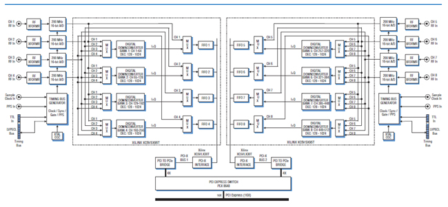
Model 7751 is a high-speed software radio board designed for processing baseband RF or IF signals from a communications receiver. It features either four 200 MHz 16-bit A/Ds (Model 7751) or eight A/Ds (Model 7751D). Each bank of four A/Ds is supported by a high-performance 256-channel installed DDC IP Core and interfaces ideally matched to the requirements of real-time software radio and radar systems.
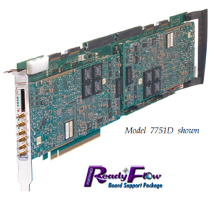
The 7751 attaches to motherboards with full length PCIe (PCI Express) interface slots for installation in various PCs, blade servers and computer systems.
A/D Converter Stage
The front end accepts four or eight fullscale analog RF or IF inputs on front panel SMC connectors at +8 dBm into 50 ohms with transformer coupling into Texas Instruments ADS5485 200 MHz, 16-bit A/Ds. The digital outputs are delivered into a Xilinx Virtex-5 FPGA for routing, formatting and DDC signal processing.
DDC Input Selection and Tuning
Each of the Model 7751 SX95T FPGAs employs an advanced FPGA-based DDC engine consisting of four identical 64-channel DDC banks. Four independently controllable input multiplexers select one of the attached four A/Ds as the input source for each DDC bank. In this way, many different configurations can be achieved including one A/D driving all 256 DDC channels and each of the four A/Ds driving its own DDC bank.
Decimation and Filtering
All of the 64 channels within a bank share a common decimation setting that can range from 128 to 1024, programmable in steps of 64. For example, with a sampling rate of 200 MHz, the available output bandwidths range from 156.25 kHz to 1.25 MHz. Each 64-channel bank can have its own unique decimation setting supporting as many as four different output bandwidths for the board.
The decimating filter for each DDC bank accepts a unique set of user-supplied 18-bit coefficients. The 80% default filters deliver an output bandwidth of 0.8*ƒs/N, where N is the decimation setting. The rejection of adjacent-band components within the 80% output bandwidth is better than 100 dB.
Each DDC delivers a complex output stream consisting of 24-bit I + 24-bit Q samples at a rate of ƒs/N. Any number of channels can be enabled within each bank selectable from 0 to 64.
Output Multiplexers and FIFOs
Four output MUXs in each SX95T FPGA can be independently switched to deliver either A/D or DDC data into each output FIFO. This allows users to view either wideband A/D data or narrowband DDC data, depending on the application.
For more information and price quotation on the Model 7751, click here or on the Model 7751D, click here.
|