| Home > Pipeline Newsletters > Model 78620 with GT-ASGM18A and GT-ASAM18A |

| ||
|
Winter 2016 Vol. 25, No. 1 | ||
Simulation of Modern Radar Systems using Pentek Model 78620 Boards with the Giga-tronics GT-ASGM18A Advanced Signal Generator and GT-ASAM18A Advanced Signal Analyzerby Mark Elo, Vice President of Marketing, Giga-tronics, Incorporated To simulate a modern, frame-based radar, a system needs to rapidly create or schedule signals that are fundamentally complex in nature and can vary considerably over time based on mission, mode, and environmental considerations. Multiple Pulse Repetition Intervals (PRIs), different types of Modulation on Pulse (MOP), as well as rapid changes in amplitude and frequency (which include the effects of Doppler, group delay, and clutter) need to be taken into account and combined with multi-mission operations such as communications, electronic attack, or counter measures scheduling. This article explores a fully modular (and COTS) hardware system that is highly reconfigurable and can be used to create emitters, not only for testing purposes, but versatile enough architecturally for rapid prototyping or for meeting the needs of fast-cycle technology procurements. Introduction: Radar SystemsA radar system can be broken down into four distinct areas of operation:
If we consider technology evolution, computer processing has technology changes yearly, signal processing and IF technology every five years, and microwave moves at a slower, ten-year pace. The four areas listed above can be mapped to physical hardware modules – each with defined characteristics and known physical interfaces – allowing the creation of a system that maps to the appropriate technology life cycles more efficiently than a traditional radar design.
Waveform Creation and Signal ProcessingThe Pentek Model 78620 high-performance PCIe board is based on the Xilinx Virtex-6 FPGA. Pentek Model 78620 is used in many EW (electronic warfare) applications, and can be mounted in most modern COTS PCs. As a multichannel, high-speed data converter, Model 78620 is suitable for connecting with the IF input of a microwave up/down-converter such as the Giga-tronics GT-ASGM18A Advanced Signal Generator and GT-ASAM18A Advanced Signal Analyzer. The Pentek Model 78620's built-in data acquisition and waveform generation features offer an ideal turnkey solution for radar and electronic warfare baseband signal simulation. 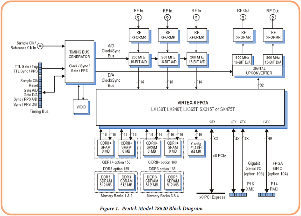 Each Model 78620 includes three A/Ds, two D/As, and four banks of memory. In addition to supporting PCI Express Gen. 2 as a native interface, Model 78620 also includes optional general-purpose and gigabit serial card edge connectors for application-specific I/O (see Figure 1). Microwave Up- and Down-conversionThe Giga-tronics GT-ASGM18A Advanced Signal Generator and GT-ASAM18A Advanced Signal Analyzer are high-fidelity, coherent, fast-frequencyswitching, up- and down-converters ideal for transmitting and receiving signals at frequencies between 100 MHz and 18 GHz. These units are based on AXIe, an open system modular instrumentation standard, which is an extension of AdvancedTCA® (a trademark of PICMG). 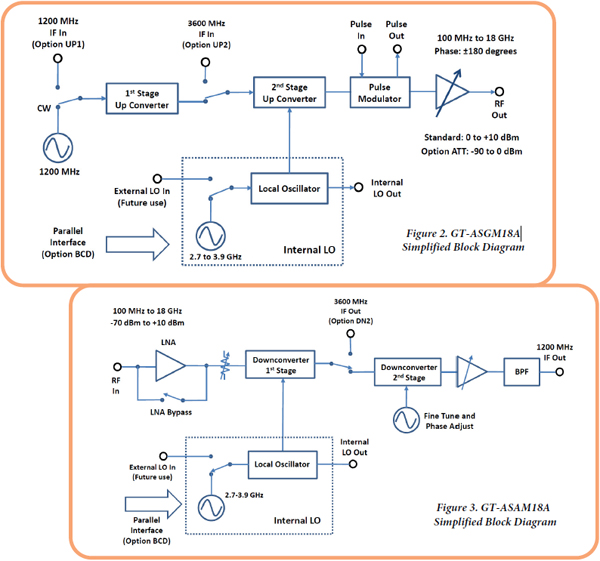 The Giga-tronics GT-ASGM18A and GT-ASAM18A have built-in, high-speed, high-signal-fidelity, local oscillators, allowing for broadband, extremely agile, coherent frequency switching. Because these units are based on the industry standard AXIe modular platform, multiple phase-coherent channels of upconversion and downconversion can be used to emulate specific types of radars or create a wave-front and emulate the angle of arrival. The Giga-tronics GT-ASGM18A and GT-ASAM18A can take an IF signal from a Pentek Model 78620 and up- or down-convert it to any frequency within an 18 GHz range. The GT-ASGM18A and GT-ASAM18A can coherently retune to any frequency in less than a microsecond and can maintain an amplitude flatness typically within +/- 1 dB over that frequency range. The optional high-speed microwave output attenuator extends the range of the output by 90 dB, allowing for a signal creation range that exceeds 100 dBc. IF ConversionMatching the IF signals from Pentek’s Model 78620 requires IF conversion to take a 30 MHz IF signal chosen to utilize the best performance from the 78620 and match that to the 1200 MHz IF of the microwave up- and down-converters. The Giga-tronics GT-SRM100A System Reference Module provides 10 MHz, 100 MHz, and 1200 MHz outputs that can be used as LOs (local oscillators) to drive IF up- and down-converters, as shown in Figure 4. 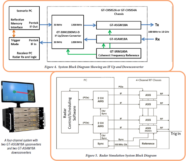 Putting it all TogetherFigure 5 shows an example system using four independent RF channels. A similar block diagram can be used for the receiver. The radar control and scheduling software schedules the waveform playout times, and a LAN connection from the receiver PC and RF subsystem determines the next mode (PRI or waveform) based on the nature of the received signal. The waveforms are scheduled within the Pentek Model 78620 AWG (arbitrary waveform generator) and the frequency and amplitude of the waveform is controlled in real time across PCIe. Optionally, fine timing resolution can be maintained by taking a trigger line from the Pentek boards and using that to deterministically control frequency and amplitude changes in the RF chassis. ConclusionsA range of radars and radar emulators, from simple single-channel radars to complex multichannel frequency-agile radars, can be created using state-of-the-art waveform creation and processing technologies. All the hardware components are commercially available off-the-shelf and no custom hardware is required. Testing complex devices, such as radar warning receivers or electronic counter measure systems, is simplified with this platform approach, and new types of radar prototypes can be rapidly created and shared between various programs. For more information about the GT-ASGM18A and GT-ASAM18A, contact Giga-tronics (email asg-info@gigatronics.com) and contact Pentek (call John Eklund at 201-818-5900 or email SDL-sales@mrcy.com) for the Model 78620.
| ||
 |
| CONNECT ON SOCIAL: |
|
|
|
|