VPX and VXS: System-level Development Strategies
As evolutionary enhancements to the venerable VMEbus, both VXS and VPX deliver significant improvements in data bandwidth, connectivity, power distribution, and cooling. When VME was first introduced, its shared bus backplane interboard transfer rates of 30 or 40 MBytes/sec was more than adequate for most applications. As requirements grew, VME acquired new interfaces such as VSB, RACEway, RACE++, VME64, VME320, and 2eSST, thereby ensuring a healthy community of suppliers and a new stream of products.
Well into its third decade of widespread deployment, VME adopted the new VXS gigabit serial interface, clearly representing the most significant leap in backplane data transfer rates throughout its entire history.
Because VXS delivered such a dramatic improvement in embedded system performance, the use of gigabit serial technology was extended to create VPX. The OpenVPX initiative followed shortly thereafter as risk-averse government agencies, with concerns about the longevity and maintainability of new technology and architecture, mandated the need for industrywide standards. The hallmark of any successful standard is that it continues to evolve with technology, and none offers a better example than VME’s evolution to VXS and VPX.
VXS: High-Bandwidth Fabric for VME
Motorola’s VME Renaissance announcement in 2003 unveiled the new VXS initiative, officially designated VITA 41 by the VSO (VITA Standards Organization). It defines the implementation of gigabit serial technology for VME in a logically layered specification, while carefully preserving the legacy VME form factors and bus operations. At the top layer, VITA 41 defines the connectors, pin designations, dimensions and mechanical structures for cards and backplanes—completely free of any mandates for specific slot interconnection strategies, protocols or fabrics.
VXS defines two types of cards: the Payload Card and the Switch Card. Both utilize the same mechanical outline as a standard 6U VME card. The payload card fits a new gigabit serial connector (MultiGig RT2) between the existing P1 and P2 connectors, designated as P0. Most legacy VME backplanes provide clearance for the new P0 connector, thus allowing insertion of VXS cards for backwards compatibility even though the VXS interface is not engaged.
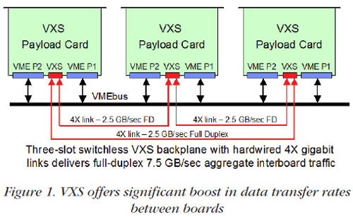
VXS backplanes have one mating MultiGig RT2 connector for each payload card slot. VITA 41 does not dictate any specific backplane topology and leaves plenty of flexibility for various architectures. The simplest configuration is the VXS switchless mesh backplane shown in Figure 1. Here, three VXS cards are joined in a ring configuration, with each card connected to the other two through two 4X links hardwired in copper as part of the backplane design. At a serial bit rate of 3.125 GHz, this system supports simultaneous data transfers among the three cards in both directions at an aggregate interboard rate of 7.5 GBytes/sec.
VPX Extensions: Tremendous Switched-Fabric I/O Capacity
With each new generation of powerful, high-performance embedded solutions— including processors with higher clock rates and wider buses; data converter products with higher sampling rates; and FPGAs, RISCs, and DSPs offering incredible computational rates—an equally capable backplane solution was needed to keep pace with the data transfer rates and prevent system bottlenecks. By extending the use of gigabit serial links already proven under VXS, the embedded community created the VPX initiative, which was formally defined under VITA 46. As a migration from the earlier VME and VXS standards, VPX shares the same outline as 3U and 6U cards and supports XMC mezzanine modules defined under the VITA 42 standard.
While VXS allows only one MultiGig RTS connector on a 6U card, VPX extends that number to three for a 3U card and to seven for a 6U card. As a result, VPX payload cards support a much higher traffic bandwidth than VXS, with eight to 24 gigabit serial 4X ports compared to only two with VXS.
Like the VXS specification, the VITA 46.0 VPX base specification does not define backplane topologies or specific gigabit serial fabrics or protocols. As with VXS, implementations of each fabric protocol are defined as sub specifications, or “dot specs.”
As industry started using VPX, a new extension emerged to deal with severe environmental requirements. The VITA 48 REDI (Rugged Enhanced Design Implementation) defines specific mechanical designs for enhanced thermal management using forced air, conduction cooling, and liquid cooling methods. It also defines protective metal covers for the cards to satisfy new requirements for simplified field servicing in deployed military applications.
OpenVPX
The OpenVPX organization was formed in January 2009 to promote industry-wide standards and long-term availability of VPX technology across the industry. The original VPX specification was being used, but because it permitted such a wide range of architectures, VPX systems tended to be unique, vendor-specific implementations.
The mission of OpenVPX was to enhance the original VPX standard by adding a set of well-defined system architectures, nomenclature and conventions to enable interoperability among vendors. Consisting of key vendors in the embedded-system community, all eager to convince government and military customers that VPX was suitable for current and future systems, the group made fast progress and turned over the completed specification to the VSO in October 2009 for standardization under VITA 65. In February 2010, the specification was ratified by VSO, while ANSI approval is expected sometime later in 2010.
The OpenVPX Language for Standardization
OpenVPX defined new nomenclature for systems to describe the gigabit serial links in terms of the number of lanes and their function. The term “pipe” is used to define the number of bidirectional differential serial pairs that are grouped together to form a logical data channel. Pipe sizes range from one lane (1X) called an “ultrathin pipe” or UTP, up to 32 lanes (32X) called an “octal fat pipe” or OFP. The popular 4X link is called a “fat pipe” or FP.
OpenVPX also categorized the different kinds of traffic carried though the pipes as “planes”. The five planes defined are the utility, management, control, data and expansion planes.
In order to define architectural characteristics of systems, several “profiles” were defined. A slot profile specifies the pipes and planes found on the backplane connectors of each slot. The module profile specifies the pipes, planes, fabrics and protocols implemented on each card. The backplane profile defines how the slots are connected to each other by pipes. And finally, the development chassis profile includes the backplane profile and defines the dimensions, power supply, and cooling method.
VPX and VXS Products
|
Dozens of embedded computer hardware vendors have developed numerous VXS and VPX products. These include backplanes; complete card cages and chassis; A/D and D/A converters; software radio cards; XMC carriers; single board computers; DSP, and RISC array processors; FPGA cards and memory cards.
VXS fully supports PMC mezzanine modules and the gigabit serial extension for PMC modules known as XMC. Both 3U and 6U VPX modules are also compatible with the gigabit XMC interface. The enormous base of existing PMC and XMC I/O modules offers integrators many choices for their VXS and VPX application solutions. Integrators can immediately take advantage of a rich variety of offerings in the market.
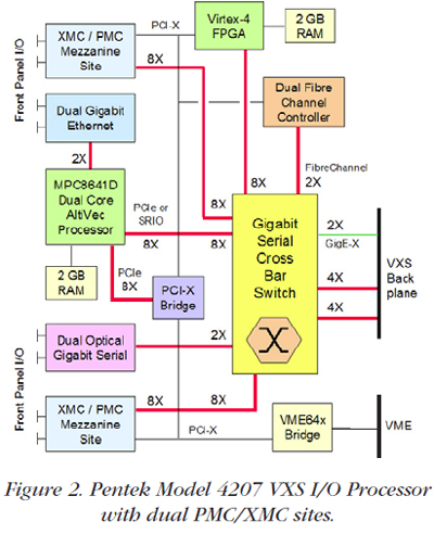
As an example, Figure 2 shows the Pentek Model 4207 VXS PowerPC I/O processor with dual XMC sites and a wealth of critical interfaces for high-performance embedded systems. At its heart is an on-board fabric-transparent gigabit serial crossbar switch. This switch highlights the vital role of serial technology for interconnecting resources within the board and to other boards across the backplane.
| |
|
VPX Applications
The latest embedded system designs show a definite shift towards serial fabricbased system architectures. These use both PCIe and SRIO, primarily to improve boardto-board data transfer rates that handle higher signal bandwidths, more powerful FPGAs and processors, and faster peripherals.
VPX cards in 3U and 6U sizes can support one or two XMC modules, respectively. Native PCIe and SRIO gigabit serial interfaces on these XMCs are often directly compatible with processors, other devices on the carrier board, and also with VPX backplane control and data planes. Other XMC protocols like Xilinx Aurora are ideal for raw high-speed data links, often directly connectable to VPX data and expansion planes.
Because they deliver substantial performance benefits, the latest FPGAs and gigabit serial fabrics increasingly dominate embedded system designs. Although these technologies are prevalent in both VXS and VPX platforms, VPX offers a clear advantage, not only because it offers many more links, but because it also simultaneously accommodates multiple protocols.
For example, GigE can handle system management, while PCIe can be used for command and control. Serial RapidIO can support high-speed data transfer between processors, while Aurora can enable FPGAs to communicate raw data across the expansion plane.
Beamforming Systems for Improved Performance
Beamforming applications use an array of antennas to improve directionality of reception and signal quality. The signal arrival delay at each antenna is based on the path distance from the source. The beamforming process adjusts the gain and phase of each antenna signal to cancel the delay differences for signals arriving from a particular direction.
Aligned signals are summed together to produce high signal-to-noise reception in the chosen direction. By adjusting gain and phase in each path, the antenna is electronically “steered” without the need for moving mechanical structures.
Examples of applications that use beamforming include Direction Finding, where a beamformed antenna can be steered to locate the arrival angle of a signal. Two or more arrays can be used to triangulate the exact location of the source. This is extremely important for signal intelligence and counter terrorism efforts.
Radar Receiver applications use both one- and two-dimensional antenna designs for phased-array and SAR (Synthetic Aperture Radar) systems. Electronic steering of the array dramatically improves the angular agility, range and target resolution of airborne antennas.
Missile detection and countermeasure applications use beamforming to improve tracking an object for early detection and improved responsiveness. And lastly, beamforming allows spatial frequency sharing by commercial mobile phone carriers because it divides the cell into several beamformed sectors.
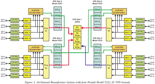
Figure 3 shows a 16-channel Beamformer using four Pentek Model 5353 3U VPX boards. This digital beamforming system takes advantage of the expansion plane for cascading beamformed data between cards.
Each of the four modules digitizes four IF signals from four antennas in the array. Four DDCs (digital downconverters) translate the IF signals to baseband and perform beamforming phase and gain adjustments.
A summation engine accepts a propagated sum from a previous card, adds the four channels from the local card and then generates a new sum signal for delivery to the sum input of the next card in the chain. The summation paths use Aurora 4X gigabit serial links for the expansion plane connections across the backplane.
VPX and VXS Summary
While VPX systems can deliver aggregate transfer rates much higher than VXS, a vast majority of system requirements can be fully satisfied by the tremendous boost in rates that VXS offers over the legacy VME. Investments made by board vendors and system integrators in VXS hardware, interfaces, middleware, software and applications will translate easily into VPX, when system needs dictate.
With so many VPX-compatible products available today, and with the new OpenVPX VITA 65 standardization, system integrators can feel confident selecting VPX architectures for high-performance embedded applications.
Further evidence that the industry has embraced VPX are two new extensions. The VITA 66 Fibre Optic Interconnect specification for VPX defines a family of Fibre-optic interconnects that allows VPX connectors J2 though J6 to be replaced with optical connectors. The VITA 67 Coaxial Connector specification for VPX defines a shielded coaxial analog RF connector using the same mechanical dimensions as VITA 66. DRS Signal Solutions is leading the VITA 67 initiative and Pentek is actively teaming with DRS on specification acceptance and product development.
VPX dramatically improves embedded system performance and can achieve rates previously unattainable with earlier technology. For all of these very tangible considerations, VXS and VPX will dominate as the preferred architectures for future high-performance commercial and military embedded systems.
|