| Home > Pipeline Newsletters > Cobalt Board Helps Researchers Improve Brain Connectivity Studies |
 | |||||
|
Spring 2012 Vol. 21, No. 1 | |||||
|
Cobalt Board Helps Researchers Improve Brain Connectivity Studies The Medical College of Wisconsin (MCW) has received a grant from the National Institutes of Health to study brain connectivity, the way signals are conveyed between regions of the brain. With this grant, researchers will develop new technologies in functional connectivity magnetic resonance imaging (fcMRI). Brain connectivity is an emerging field in neuroscience that is expanding rapidly. Brain connectivity is suspected to be a key indicator in some diseases such as schizophrenia, Alzheimer's, and Parkinson's. Some DefinitionsMagnetic resonance imaging (MRI) is a medical imaging technique to visualize detailed internal structures. MRI makes use of the property of nuclear magnetic resonance (NMR) to image the nuclei of atoms inside the body. An MRI machine uses a powerful magnetic field to align the magnetization of some atomic nuclei in the body, and RF fields to alter the alignment of this magnetization. This causes the nuclei to produce a rotating magnetic field detectable by the scanner. This information is recorded to create an image of the scanned area of the body. Magnetic field gradients cause nuclei at different locations to rotate at different speeds. By using gradients in different directions, 2D images or 3D volumes can be obtained in any arbitrary orientation. Functional magnetic resonance imaging (fMRI) has been around for about 15 years. It is an MRI procedure that measures brain activity by detecting associated changes in blood flow. This is a specialized brain and body scan used to map activity in the brain of humans or animals by imaging the change in blood flow related to energy used by the brain cells. In the last ten of those years a revolutionary method has been developing that uses this technology. This method, functional connectivity (fcMRI), has recently gained popularity for its ability to measure how brain regions interact while the subject is at rest. Being able to measure innate functional brain connectivity allows us to know if a set of regions active during a particular task is connected enough to be considered a network. We could then predict which brain regions are likely to be active together in the future. This could, in turn, motivate us to look deeper at the nature of each brain region and how it contributes to the neuron networks underlying our behavior. k-space in MRI physics is the 2D or 3D Fourier transform of the MR image being measured. Its complex values are sampled during an MR measurement controlled by a pulse sequence, i.e. an accurately timed sequence of RF pulses. In practice, k-space often refers to the temporary image space, usually a matrix, in which data from digitized MR signals are stored during data acquisition. k-space is full at the end of the scan and the data is processed to produce the final image. Magnetic resonance systems are rated in terms of the maximum magnetic field they can produce in Teslas. One Tesla (T) is equal to 10,000 Gauss which is about equal to 20,000 times the Earth's magnetic field. A Voxel is a volume element that represents a value on a grid in three-dimensional space. This is analogous to a pixel, which represents 2D image data in a bitmap. A voxel represents a single sample, or data point, on a regularly-spaced, three-dimensional grid. Work at the MCWThe specific purpose if the work at the Medical College of Wisconsin is to reduce the time needed for acquisition of a single volumetric echo-planar imaging (EPI) data set. For whole brain studies, a time set of these data sets is required. The methodology used in fcMRI involves the cross correlation of a seed voxel resting-state time course with other voxel time courses. In principle, every possible correlation coefficient that can be formed between pairs of voxel time courses can be of interest. Ideally, one would acquire all the time courses simultaneously to preserve coherencies of resting-state fluctuations across the entire brain. In actual testing, we can relax this requirement by setting a realistic goal to achieve a wholebrain data set in a time less than 2 seconds. Data acquisition can be accelerated by the use of partial k-space EPI. This reduces the number of partial k-space lines that must be acquired in a single image. Likewise the echo time (TE) can be shorter, which helps minimize signal dropout. This time can be further reduced by using inplane sensitivity encoding. These methods cause a degradation in the signal-to-noise ratio, since less time is used to collect the data. Multislice acquisition of 2D MR images to cover a volume of tissue, such as the brain, usually proceeds one slice at a time. The acquisition time can be reduced by acquiring two or more slices at a time. To achieve this goal, researchers at MCW designed multislice excitation RF pulses with distinct phase tagging of each slice and developed a method to disentangle the overlapping slices in the acquired data. The acquired signal is increased and SNR is improved when using multislice acquisition. This work was carried out on a GE Signa EXCITE 3 T MR Scanner using a whole body excitation coil and an axially symmetric 32-channel receive-only coil. The RF pulses were formed by the GE Scanner without the need for any other external equipment. Signal ProcessingFigure 1 provides an overview of the multislice acceleration method. The path to the image formation is indicated by the green blocks of the flow chart. There are three important events along this path:
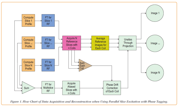 The column of connected blue and orange rectangles on the left concern RF pulse formation: the position and RF phase of each of the N individual slices are determined and the Fourier Transform (FT) is calculated assuming single excitation frequency for the slice group. For reference slices, these pulses are used independently. For aliased slices, the FT of the composite pulse is calculated by summing the N slice profiles and calculating the FT of the sum. The most important block is shown in red: short time courses of reference images are obtained for each slice N for each of the n-number RF coil arrays. The first few are discarded and the remaining images are averaged to improve the SNR. Therefore, there are N x n reference images with good SNR available, n for each of the N slices and they are complex-valued images. Finally, we arrive at the block labeled, Unalias through Projection. For each aliased voxel, a complex valued number exists from each of the n channels; in addition, the reference images provide unaliased data from the N slices and n channels for that voxel. Singular value decomposition is used to solve the system of linear equations on a voxel-by-voxel basis. Data is combined across channels in this process yielding N unaliased slices. The Pentek ConnectionWhen developing the original RF transmit pulse sequence on the GE Scanner, researchers found spurious frequencies that gave rise to ghost frequencies. Unanticipated excitation signals with amplitudes as large as 40% of the RF pulse amplitude, as seen in Figure 2A, were observed. The researchers addressed this problem by using a Pentek Cobalt® Model 78621 PCI Express board to generate the RF pulses instead of using the internal modulator of the GE Scanner. The RF pulse created by the Model 78621 has better than two orders of magnitude lower out-of-slice excitation and does not exceed 0.1% of full scale spectral amplitude, as shown in Figure 2B. 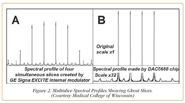 The Model 78621 dual-channel 800 MHz D/A converter was used in the interpolating mode to create RF pulses with a 2 nsec sampling rate and smooth stair-step-less modulation of the I and Q channels with 16-bit resolution. The center frequency was created by the numerically controlled oscillator (NCO) of the DAC5688 D/A converter chip. The signal is modulated by custom pulses followed by a continuous signal for acquisition reference. The modulating I and Q channels are created by harmonic functions with a continuously increasing argument. Tests showed that the phase argument of sine and cosine as large as 1019 radians still produces accurate waveforms. With a 2 nsec update time, it is good for over 500 years! This unprecedented accuracy was used to create a reference signal that compensates the phase of off-resonance frequencies used to excite different slices. The image in Figure 3A was acquired conventionally using the RF pulses created by the GE Scanner. The lack of phase coherence is obvious. The image in Figure 3B was created by the same sequence except the RF pulses were synthesized by the Pentek Model 78621 D/A converter. In Figure 3C, standard EPI phase images are shown for comparison. The phase variation across slices is apparent in Figure 3B and is in agreement with Figure 3C. This is not the case for the standard acquisition used to create Figure 3A. 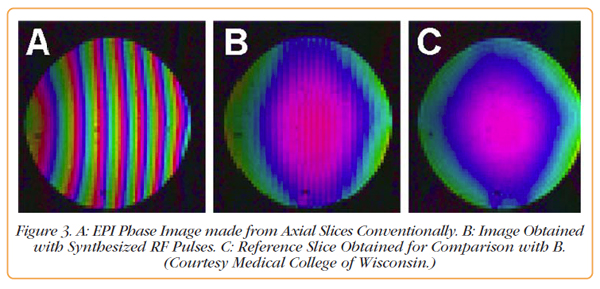 Acknowledgment
| |||||
| CONNECT ON SOCIAL: |
|
|
|
|