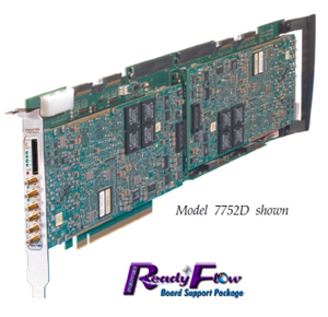
Models 7752 / 7752D 64- or 128-Channel DDC with Four or Eight 200 MHz, 16-bit A/Ds - PCIe
Features
- 32 or 64 DDC channels in banks of eight channels
- Independent 32-bit tuning for all channels
- Decimation from 16 to 8192 in steps of 8
- Bandwidths from 20 kHz to 10 MHz
- Different decimation factors between banks
- User-programmable 18-bit FIR filter coefficients
- Default filters with 0.2 dB ripple and 100 dB rejection
- Power meters and threshold detectors
- Clock/sync bus for multiboard synchronization
| |
|
General Information
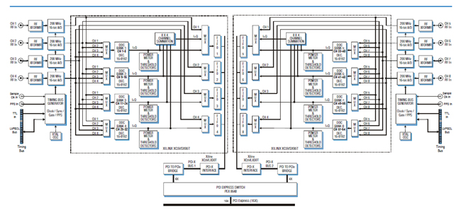
Model 7752 is a high-speed software radio board designed for processing baseband RF or IF signals from a communications receiver. It features four 200 MHz 16-bit A/Ds (Model 7752) or eight A/Ds (Model 7752D). Each group of four A/Ds is supported by a high-performance 32-channel installed DDC IP Core and interfaces ideally matched to the requirements of real-time software radio and radar systems.
The front end accepts four or eight fullscale analog RF or IF inputs on front panel SMC connectors at +8 dBm into 50 ohms with transformer coupling into four Texas Instruments ADS5485 200 MHz, 16-bit A/D converters. The digital outputs are delivered into a Xilinx Virtex-5 FPGA for routing, formatting and DDC signal processing.
DDC Input Selection and Tuning
Each of the Model 7752 SX95T FPGAs employs an advanced FPGA-based digital downconverter engine consisting of four identical 8-channel DDC banks. Four independently controllable input multiplexers select one of the four attached A/Ds as the input source for each DDC bank. In this way, many different configurations can be achieved including one A/D driving all 32 DDC channels and each of the four A/Ds driving its own DDC bank.
Decimation and Filtering
All of the eight channels within a bank share a common decimation setting that can range from 16 to 8192, programmable in steps of 8. For example, with a sampling rate of 200 MHz, the available output bandwidths range from 19.53 kHz to 10.0 MHz. Each 8-channel bank can have a unique decimation setting supporting up to four different output bandwidths for the board.
The decimating filter for each DDC bank accepts a unique set of user-supplied 18-bit coefficients. The 80% default filters deliver an output bandwidth of 0.8*ƒs/N, where N is the decimation setting. Rejection of adjacent-band components within the 80% bandwidth is better than 100 dB.
Each DDC delivers a complex output stream consisting of 24-bit I + 24-bit Q samples at a rate of ƒs/N. Any number of channels can be enabled within each bank selectable from 0 to 8. Each bank includes an output sample interleaver that delivers a channel-multiplexed stream for all enabled channels within the bank.
Power Meters, Threshold Detectors
The 7752 features up to 64 power meters that continuously measure the individual average power output of each DDC channel. The time constant of the averaging interval for each meter is programmable up to 16 kilosamples. In addition, threshold detectors automatically send an interrupt to the processor if the average power level of any DDC falls below or exceeds a programmable threshold.
For more information and price quotation on the Model 7752, click here or on the Model 7752D, click here.
|