Tools for Real-Time Embedded System Development
With each new opportunity, real-time embedded system developers confront a unique set of challenges specific to the requirements at hand. Although methodology and lessons learned in previous projects are invaluable, each new system introduces increasingly more complex hardware and software. Estimating correctly how long development will take, choosing the right approach, and selecting the appropriate tools are crucial for delivering the project on time and coming out ahead on the bottom line. Towards that end, the strategies, considerations and tradeoffs presented here should offer some useful insights.
Hardware Environment
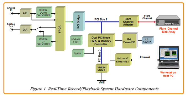
A typical real-time embedded system, like the one shown in Figure 1, includes high-speed A/D and D/A converters plus the associated circuitry for clocking, gating, triggering and synchronizing multiple channels. Digital upconverter and downconverter ASICs provide frequency translation for communications and radar applications. FPGAs handle tough real-time signal processing tasks like FFTs, encoding and decoding, encryption and decryption, modulation and demodulation, and beamforming. A fast memory, buffers signal data to support efficient block transfers to and from other system resources. Often, a fast hard disk allows the system to handle real-time storage and playback of signal data. A control processor manages system resources and often performs some additional signal processing and data formatting tasks.
Connected through an Ethernet link, a host PC workstation running Windows or Linux provides essential non-real-time hardware resources for the operator interface including a monitor, keyboard and mouse. The PC also provides high-capacity disk storage for archiving data files and network connections to the office or facility.
All the necessary hardware components are present, but which software components will ensure that the system performs the way it should?
Software Considerations
A good choice for the real-time control processor is usually a DSP or RISC processor. It should be free of tasks not directly related to essential data movement, formatting or processing. During real-time operation, there should be minimum interaction with the PC. However, before and after real-time operations, the Ethernet link can be extremely useful for initializing the real-time hardware, configuring modes of operation and for moving data between the real-time disk and the PC disk file system.
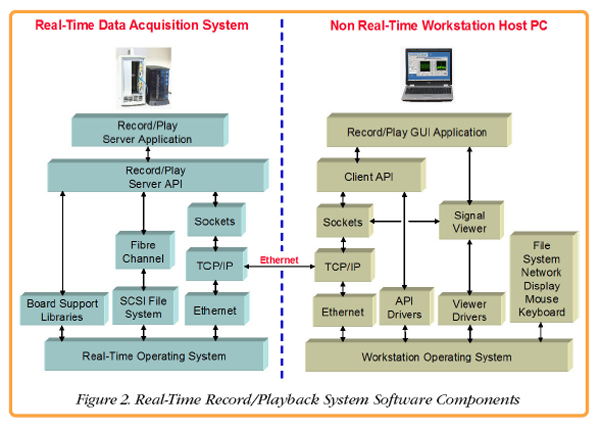
Figure 2 is a proposed software model for the high-speed real-time recording system shown in Figure 1, partitioned into real-time and nonreal-time domains and joined by Ethernet. While this diagram looks complicated at first, each software module serves a welldefined, essential function to maintain performance while easing software development tasks.
Inside the Real-Time System
The real-time system on the left side of Figure 2 uses a real-time operating system (RTOS) with low latencies and deterministic behavior to guarantee that no data will be lost while managing the critical tasks it needs to perform. The Board Support Libraries feature well-defined subroutine calls to implement low-level control for all of the real-time front-end hardware resources. This includes configuring the A/Ds and D/As, setting parameters for the digital up- and downconverters, and defining modes in the timing section for triggering, gating and synchronization.
The SCSI file system uses RTOS calls to manage real-time transfer to and from the local Fibre Channel hard disk. A Fibre Channel protocol layer provides a complete high-speed file system interface suitable for real-time recording and playback.
Nearly every RTOS also provides a native stack for Ethernet, TCP/IP drivers and support for sockets, a very popular application layer protocol for networks.
Each of these three resource groups— the Board Support Libraries, the Fibre Channel interface and a network socket interface— are integrated by the Record /Play Server API (Application Programming Interface) into a set of intuitive high-level functions to simplify development of custom server applications.
The Record/Play Server Application on top, acting as the executive in charge, has complete access to generate and receive Ethernet commands and status, directing real-time data streams on and off the Fibre Channel hard disk, and controlling all operating parameters and modes of the front end data acquisition hardware.
With these software components, the real-time hardware has now assumed the role of a complete, stand-alone functional server subsystem. It is capable of responding to Ethernet commands that are interpreted by the server application and then dispatched efficiently by the server API. When the function is complete, the server application can issue an Ethernet message along with any relevant parameters about the operation.
By extending the code in the server application so that it understands and implements different or more complex commands, the real-time subsystem can acquire new features. These new commands simply implement a new set of calls to the existing collection of Record/Play Server API functions. For example, a new Ethernet command might fetch data from the Fibre Channel disk and deliver back through the Ethernet port.
Inside the Workstation PC
The Workstation PC on the right side of Figure 2 assumes the role of the client, by sending and receiving Ethernet messages to and from the real-time server subsystem. Virtually all workstation operating systems include native support for Ethernet, TCP/IP, and sockets to support the message transfers.
The Client API manages the socket message traffic by appropriately forming outgoing Ethernet commands so they are understood by the real-time server and interpreting status messages that are returned by the server. Like the Record/Play Server API, it presents a set of easy-to-use highlevel commands suitable for client user applications.
Additional socket connections deliver Ethernet data from the server into the Signal Viewer. This application delivers a graphical representation of signals on the PC screen, providing the operator with an oscilloscope display for viewing signal data. This can be useful for checking snapshots of live data from the A/D converter before recording, for verifying the live output of a digital downconverter, and for viewing the data recorded on the Fibre Channel hard drive after the recording.
Any such operations required by the client application, must first be implemented in the client API and then supported as formal commands by the server application. Of course, the necessary functions to execute those commands need to be available in the Record/Play Server API. If not, additional API functions can always be created as required. One typical client application is a virtual panel GUI (graphical user interface) displayed on the monitor. With buttons, knobs, sliders, switches, indicators, status windows and parameter entry windows, the operator simply uses the mouse and keyboard to control operations. Such an application can be written in Visual C, Visual Basic or JAVA to make a visually attractive and functional layout. The GUI would make the appropriate calls to the client API according to which buttons are pushed or which parameters are entered.
Another type of client application could be a larger application that needs a record/play subsystem as an I/O resource. In this case, the larger application might be written in C or C++, or any other language supported by the operating system. Like the GUI, it would also make calls to the client API to setup up the hardware, start and stop the recording and then fetch data back into the application. By adding this type of functional subsystem that is easy to use and fully characterized, system developers can slash development time and reduce risks.
The rationale for each of the many software blocks shown in Figure 2 should now be appreciated. The modular architecture of this system helps custom application developers to take advantage of the standardized, well-defined interfaces between the modules to add new features, commands and functions. The existing commands and subroutine structures offer excellent examples for building new ones that are fully compliant with the rest of the system. Operating system revisions, maintenance upgrades, and ports to different operating systems all benefit from this modularity.
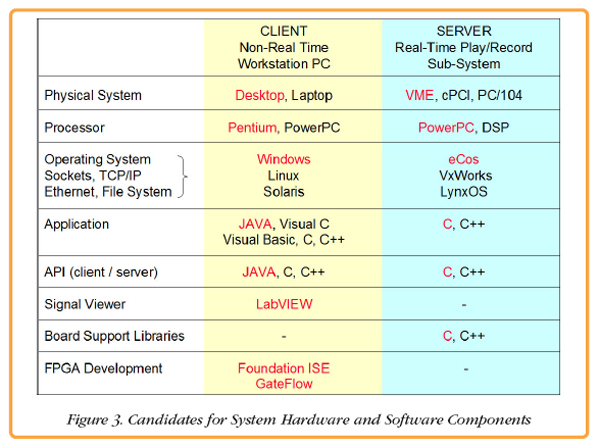 Figure 3 shows some appropriate candidates for the various modules discussed to illustrate the many choices available. Client workstation platforms for these systems range from handheld devices, blade servers, embedded PCs, laptops, and desktop PCs to networked clusters of high-end multiprocessing systems. In each case, the processors must support a diverse set of infrastructure functions best handled by operating systems like Windows, Linux, Unix, or Solaris.
Client applications and the client API can be written in C or C++, and GUI components can use visual versions of these tools. A popular trend towards using JAVA for both the client applications and API helps with portability across platforms and operating systems. The signal viewer application is an ideal candidate for LabVIEW which offers tools specifically oriented towards signal processing and display, and is now available for many workstation environments.
By its nature, the real-time server system is less heterogeneous and runs under operating systems like VxWorks, eCos, or LynxOS. Most of the components, including the board support libraries, server application and API, and the network and disk drivers are all written in C or C++, with some lower level functions coded in assembly language.
Putting It All Together
|
Pentek's SystemFlow® is an implementation of this software framework. It was developed to address hardware platforms like the real-time recording/playback system of Figure 1, which is similar to the Pentek Model 2504 high-speed real-time recorder/playback system.
SystemFlow includes the software modules shown in Figure 2 written with the software tools highlighted in color in Figure 3. By following this proposed software architecture, SystemFlow successfully fulfills two different product objectives for the same hardware: 1) a ready-to-use record/playback system, and 2) a high-speed real-time signal processing development platform.
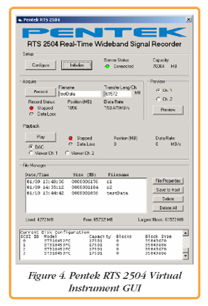
To meet the needs of the record/playback system, special enhancements were made. These include a complete virtual GUI, a real-time file manager, and a full-featured signal viewer. The workstation GUI, shown in Figure 4 on the next page, was written in JAVA and runs under both Windows and Linux.
Intuitive buttons, indicators, status windows and parameter entry windows are geared for novice users who simply want to capture signals and transfer files to their workstation.
| |
|
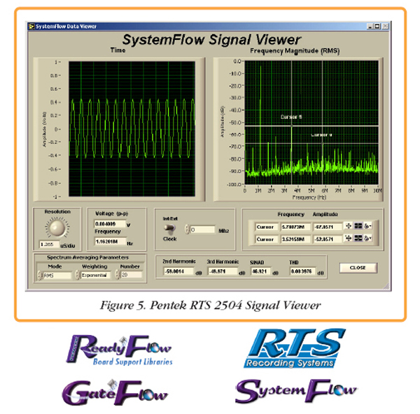 A sophisticated File Manager, implemented through extensions to both the client API (also written in JAVA) and the server API (written in C), supports usernamed files and headers that automatically store important system parameters in each recording. The client Signal Viewer shown in Figure 5 is written in LabVIEW and includes display windows for both time and frequency domains, dual annotated cursors, and automatic calculation of critical signal parameters such as harmonic distortion and signal to noise ratio.
To meet the alternate needs of a real-time signal processing development platform, SystemFlow includes source code for the software modules that were created for the record/play system. System developers can start with this fully functioning high-speed system and incrementally extend, replace, or modify each module as required to meet the custom requirements they need.
For customizing workstation modules, JAVA source is provided for the client GUI application and client API, and the LabVIEW script is provided for the Signal Viewer.
For customizing server modules, a complete eCos development environment running under Windows offers license-free, open-source tools including the GNU compiler, Insight for the GDB debugger, CYGWIN make utilities, an eCos kernel configuration utility, and a TFTP server. C source code is supplied for the record/play server application and server API, the file manager and the socket interface. Pentek ReadyFlow Board Support Package include C source code for the data movement, mode and parameter initialization, timing and control of all hardware resources on the boards.
For FPGA code development, the Xilinx ISE Foundation Tool Suite is installed in the Windows workstation. The GateFlow® FPGA Design Resources contain all ISE project files and VHDL source code for the specific hardware boards. In this way, FPGA developers can build upon the standard interfaces and structures already instantiated. An FPGA code loader utility transfers newly created FPGA bit streams through the Ethernet link into the FPGA.
All software development tasks for the workstation, the real-time server, and the FPGAs are performed on the Windows workstation. All real-time server development tasks are supported across the Ethernet link through drivers and utilities. Except for the optional Xilinx ISE tools and GateFlow® FPGA Design Resources, all these resources are bundled into the SystemFlow package.
The unique requirements of each real-time embedded system will drive choices in the hardware, the nature and function of the software modules, the operating systems and software languages. However, the philosophy of the software architecture outlined here should prove valuable in helping you make those decisions when starting your next design.
|