| Home > Pipeline Vol. 15 No. 3 > Taking another Look at Gravitational Waves |
| ||||||||
|
Fall 2006 Vol. 15 No. 3 | ||||||||
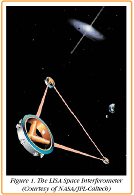
Taking another Look at Gravitational WavesIn the summer 2002 issue of The Pentek Pipeline, we reviewed the Laser Interferometer Gravitational-wave Observatory (LIGO) in the article Looking at Gravitational Events of Cosmic Origin. LIGO is aimed at searching for gravitational waves created by supernova collapses of stellar cores that form neutron stars and black holes, collisions and consolidations of such neutron stars and black holes, and the remnants of gravitational radiation created by the birth of the universe. To read the full article in that issue, please click here: LIGO. The existence of these gravitational waves was predicted by Einstein's theory of general relativity. Gravitational waves are ripples that propagate through the universe. They are roughly analogous to electromagnetic waves, except what is "waving" is space time itself. Efforts to detect gravitational waves have been going on for roughly one-half century, but the measurements themselves are very difficult to make and no confirmed detections have been made yet. LIGO InterferometryAs in the case of LIGO, most modern detection efforts use a technique known as interferometry: start with a laser beam, split it into two beams and send each of these two in a different direction. After some distance, reflect each beam with a mirror and return it to a central detector that's used to measure the distance to the mirror at the far end. A gravitational wave passing by will cause minute changes to the distances between the mirrors. Since space itself is stretching, the amount of displacement is directly proportional to the distance between the mirrors. Scientists use the term "strain" to describe this change in length between mirrors divided by the original length. Typical expected strain amplitudes resulting from gravitational waves are in the order of 10–22. Ground-based interferometers such as LIGO are approximately 4 km long. They must measure something with an amplitude spectral density on the order of 10–19 m/vHz at 1 kHz. This is about 1000 times smaller than the radius of a proton! A Space Interferometer
Quick Facts about LISA.
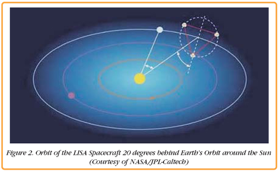 LISA InterferometryLISA will not only be the world's largest interferometer, it will be the laser interferometer with the world's largest arm length difference. This arm length difference presents one of the most challenging problems of LISA. Fluctuations in the laser frequency in a standard Michelson interferometer, scale with the arm length difference and produce a noise background which could limit the sensitivity of the interferometer. A direct Michelson interferometer type measurement would require that the fractional frequency stability of the laser be less than or equal to the strain we are trying to measure. Taking all these parameters into account, the required laser frequency stability is on the order of a few µHz/vHz at 1 mHz. Use of the best materials and stabilization control systems, can reduce the laser frequency noise into the 1Hz/vHz range. It is expected that the temperature fluctuations on the LISA spacecraft will be in the same range and that the laser frequency noise in LISA will also reach the Hz range. The remaining noise would be about six orders of magnitude above the required noise level for a direct Michelson interferometer measurement. Several solutions to reduce this noise further have been proposed. The most favored solution uses a technique called Time Delay Interferometry (TDI) to create an artificial equal arm length Michelson interferometer. It detects fluctuations in the two arms of the interferometer independently from each other and then forms linear combinations between the instantaneous signals and earlier measured (time delayed) signals. This linear combination will be insensitive to laser frequency noise, just like the interferometer signal of an equal arm length Michelson interferometer. Arm locking is another solution. The idea is to use the arms of the LISA interferometer as the reference for the laser frequency and stabilize or lock the laser frequency to this reference. This elegant solution has the disadvantage that the long light travel times between the spacecraft, put severe constrains on the feedback loop and it is unlikely that the loop alone will have enough gain to suppress the entire laser frequency noise to the required level. However, a partial suppression of the laser frequency noise could significantly reduce the very tight requirements on TDI. The LISA SimulatorA full test of TDI or arm locking depends on the capability to simulate the long light travel time between the LISA spacecraft. Until recently, it was assumed that this was impossible; that experimental tests could only be performed at the subsystem level; and that only simulations can bridge the gap to the final instrument.
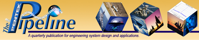
A simplified design of the optical bench is shown in Figure 4. The majority of the beam from Laser 1 is reflected at a polarizing Beam Splitter and sent out to the far spacecraft. The same setup is located within the far spacecraft and directs another beam, from Laser 2, toward the bench of Laser 1. The telescope is used to gather the light of the diverged beam from Laser 2 and direct it onto the proof mass. 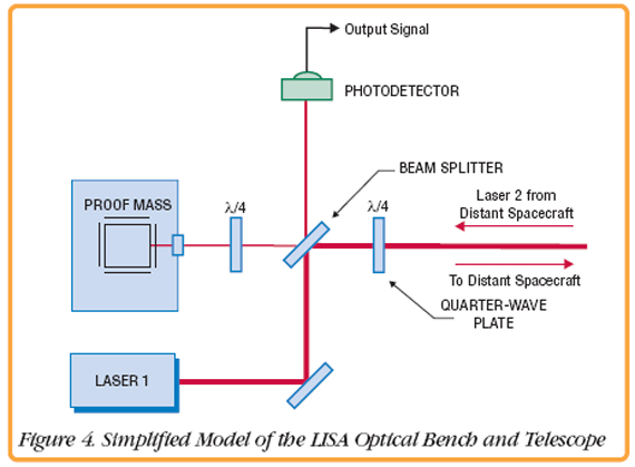 The Photodetector (PD) on the bench measures the beat signal between Lasers 1 and 2. The output signal will have a frequency equal to the difference frequency of the lasers, plus terms due to phase noise of the lasers and the travel time of light between the spacecraft. Electronic Phase DelayAny experimental verification of LISA interferometry requires a way to simulate the significant light travel time between the spacecraft. The EPD under development by the researches at UF, will delay signals in real-time within an optical setup. As shown in Figure 5, Laser 0 is used as a reference and beats with Lasers 1 and 2. The difference frequencies between the lasers seen by the photodetectors are in the range of 10–20 MHz and contain a large amount of frequency or phase noise, very similar to the expected noise in LISA. The signal from PD 2 is first filtered by an antialiasing low-pass filter and then digitized by one of the channels of a Pentek Model 6256 Four-Channel 14-bit, A/D Converter VIM module with dual Xilinx Virtex-II FPGAs. 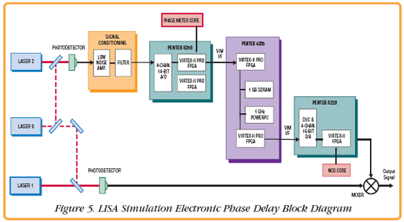 The digital signal is then routed to one of the FPGAs, where a Phase Meter IP core is implemented. Here, the signal is mixed with both the I and Q quadratures of a sinusoidal signal generated onboard the FPGA by a Numerically-Controlled Oscillator (NCO). The two signals are then low-pass filtered to obtain the I and Q components of the input signal. This processing is required because the input phase noise is so large that it would wrap over many cycles. Consequently one of the quadratures is used as an error signal to adjust the phase of the NCO to keep the mixers in their linear ranges and remove any phase ambiguity from the signal. The desired signal is the phase of the input signal which is obtained by properly combining the local oscillator signal to the NCO with the residual phase difference between the input and the NCO. This, along with the amplitude of the signal, is then downsampled to a lower rate and transmitted across the VIM-2 interface to the Model 4205 carrier board. From the Model 4205, the data is streamed across the Ethernet interface to a PC for storage and analysis. In addition, the data is stored in the Model 4205 SDRAM to mimic the light travel time delay. The output of the SDRAM is then transmitted across the VIM interface to the Pentek Model 6228 Digital Upconverter and D/A VIM module, where an NCO core implemented in the FPGA upsamples the data and recreates the waveform with the delayed phase and amplitude of the original input signal. This analog output is then mixed and demodulated with the non-delayed beat signal between Laser 1 and 0. The demodulated signal is technically identical to a LISA optical bench signal. For more information on LISA, click here.
| ||||||||
 |
| CONNECT ON SOCIAL: |
|
|
|
|